The German Aero Space Center integrates Outsight to fuse GNSS data with LiDAR
The Institute of Traffic System Technology at DLR explores the fusion of GNSS and SLAM methods to achieve robust and geo-referenced localization in dynamic urban traffic.

In the quest for precise perception amidst modern cities’ bustling streets, self-driving cars face a unique challenge.
This article showcases the successful fusion of GNSS and LiDAR solutions thanks to Outsight's processing software integrated into the work of the Institute of Traffic System Technology at the German Aero Space Center, enabling safe navigation through even the tightest construction sites, a feat unattainable with GNSS alone.
Introduction
In the realm of self-driving cars, two primary approaches emerge: the full perception-based method, striving to replicate human-like awareness by constructing a comprehensive digital representation of the environment, and the map-based approach, reliant on high-precision geo-referenced maps for localization and trajectory planning.
GNSS solutions excel in accuracy but falter in urban areas due to signal interference, while SLAM relies on local sensor data to create virtual maps. To address this, this research combines GNSS and SLAM, achieving accurate geo-referenced localization with varied SLAM map transformations.
Developed in collaboration with Outsight, this approach is part of the Automated Driving test project in the city of Düsseldorf led by the German Aero Space Center.
LiDAR and GNSS Fusion
The localization strategy involves three coordinate frames: odom [for odometry], map, and utm.
Control actions occur in the odom frame for smooth car operation, while planning relies on the drift-free map and utm frames.
Outsight’s LiDAR-based SLAM map and Relocalization is used to address GNSS's limitations, offering robustness through environmental perception.
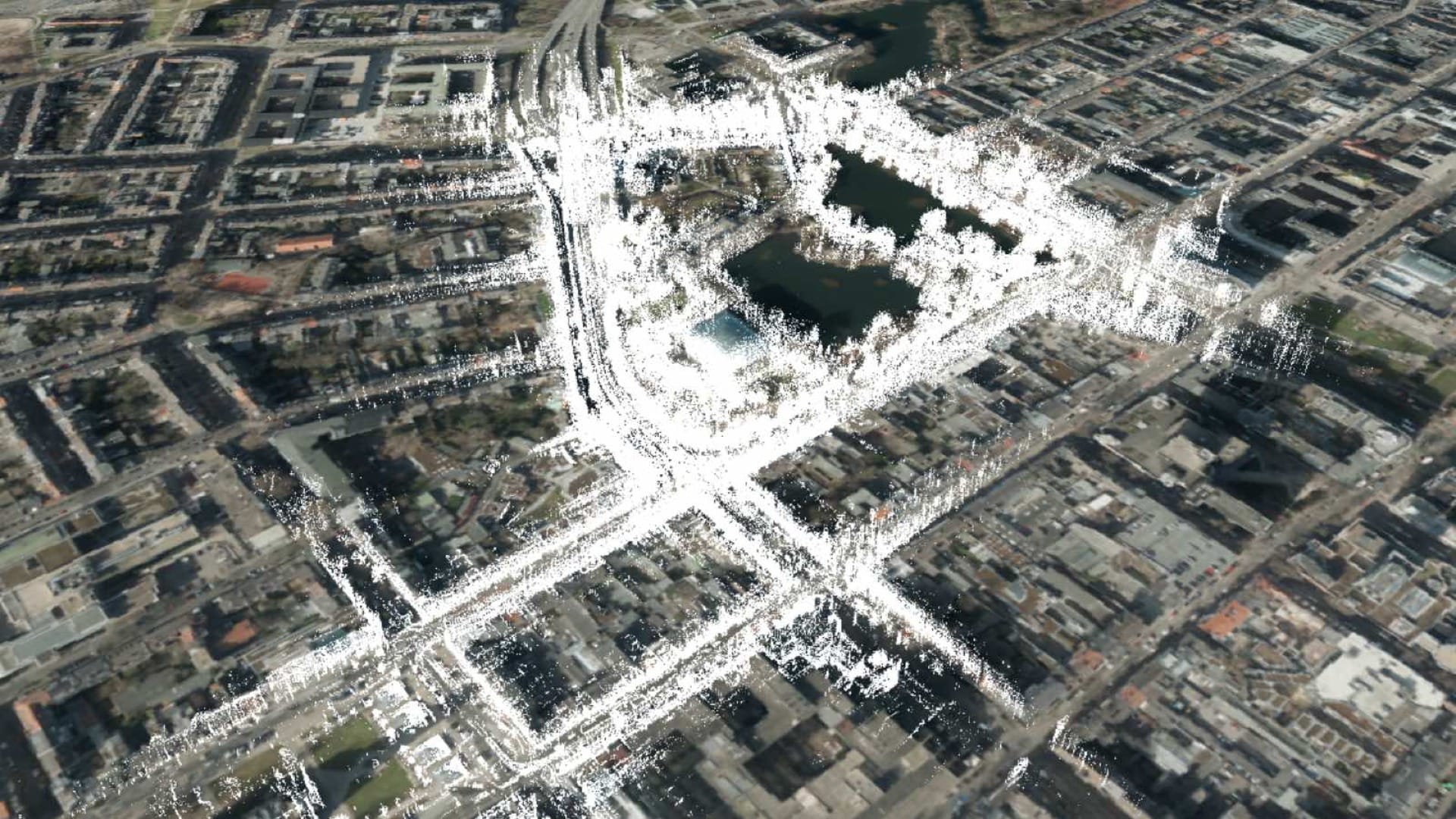
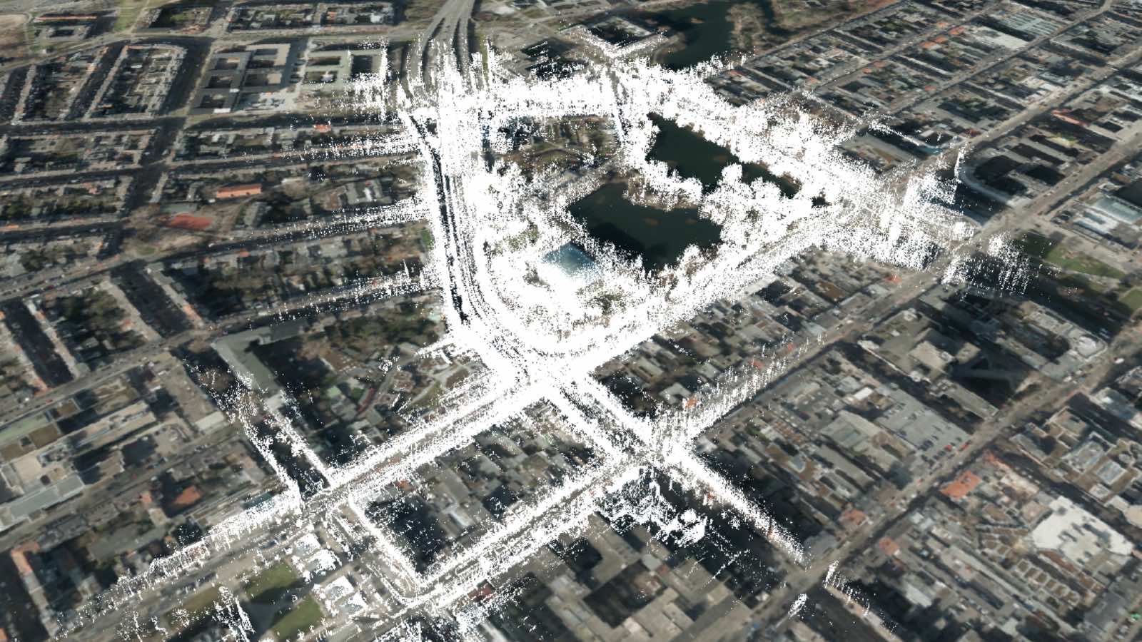
Step 1: Map generation
Outsight's map generation algorithm employs LiDAR-based SLAM (no IMU required).
During LiDAR data recording, the algorithm is supplemented with WGS 84 coordinates of the sensor's position. This creates a trajectory in the SLAM map, preserving world coordinates at each point.
Only trajectory points with precise covariance matrix norms are considered valid, ensuring accurate mapping from local SLAM to WGS84 coordinates while disregarding imprecise sections.
Step 2: LiDAR-based localization
During autonomous drives, Outsight's SLAM algorithm was used for car localization within the existing SLAM map. This approach also yields robust WGS 84 coordinates.
Assuming the initial LiDAR-based localization in the SLAM map is robust, the algorithm selects nearby points from the trajectory in the SLAM map and calculates barycentric coordinates for the current hypothesis.
These barycentric coordinates, when applied to the corresponding nearby WGS 84 points, determine the LiDAR sensor's current WGS 84 position.
Step 3: uncertainty correction
In the final step, a Kalman filter combines odometry, GNSS localization input, and the LiDAR-based GNSS solution, requiring covariance information. Since the LiDAR localization in the SLAM map lacks this data, an estimation is made.
A minimal covariance matrix is assigned to the LiDAR-based solution to ensure its error ellipse covers the GNSS-based solution without altering the ellipse's aspect ratio. This addition results in a covariance matrix with an error ellipse likely to encompass the true real-world position.
Demonstration Setup
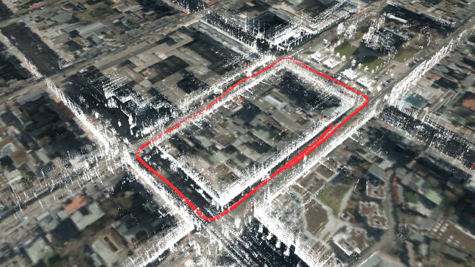
The test route, located in Düsseldorf, follows a counterclockwise path around a block of both narrow and wide streets. It encompasses junctions, and is surronded by multi-story buildings limit the sky view, diminishing GNSS precision.
The test vehicle utilized was the ViewCar2, a VW Passat from the German Aerospace Center's Institute of Transportation Research. It came equipped with various sensors for autonomous driving, with key components for localization including:
- GNSS: Comprising a Novatel SPAN OEM6 with ProPak6 receiver, a Litef μIMU-IC IMU, dual GPS antennas, and RTK correction.
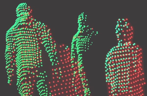
- LiDAR Sensor: A Velodyne VLP32-C with 32 layers, capable of providing around 600,000 measurements per second and operating at 20 Hz.
- ALB (LiDAR-based GNSS): An external embedded solution by Outsight. During the demo, it was running alpha firmware version 5.3.0, with all relevant features available in firmware version 5.5.0 and later.
ADORe operates based on map-oriented principles, allowing for empirical assessment of localization accuracy and errors by the driver and co-driver:
- Lateral errors can be observed as the vehicle follows the virtual lane's centerline.
- Abrupt steering maneuvers without visible obstacles often signal localization errors in the opposite direction.
- When the vehicle is at a standstill, a drifting localization solution results in errors in the estimated trajectory.
Results
Acquiring ground truth data for localization in this intricate test site proves costly. Traditional methods, such as employing a total station with a 360° prism, require an unobstructed line of sight, which is hindered by adjacent buildings.
Alternatively, utilizing infrastructure sensors to track the positions of traffic participants is an expensive and unfeasible option for this project.
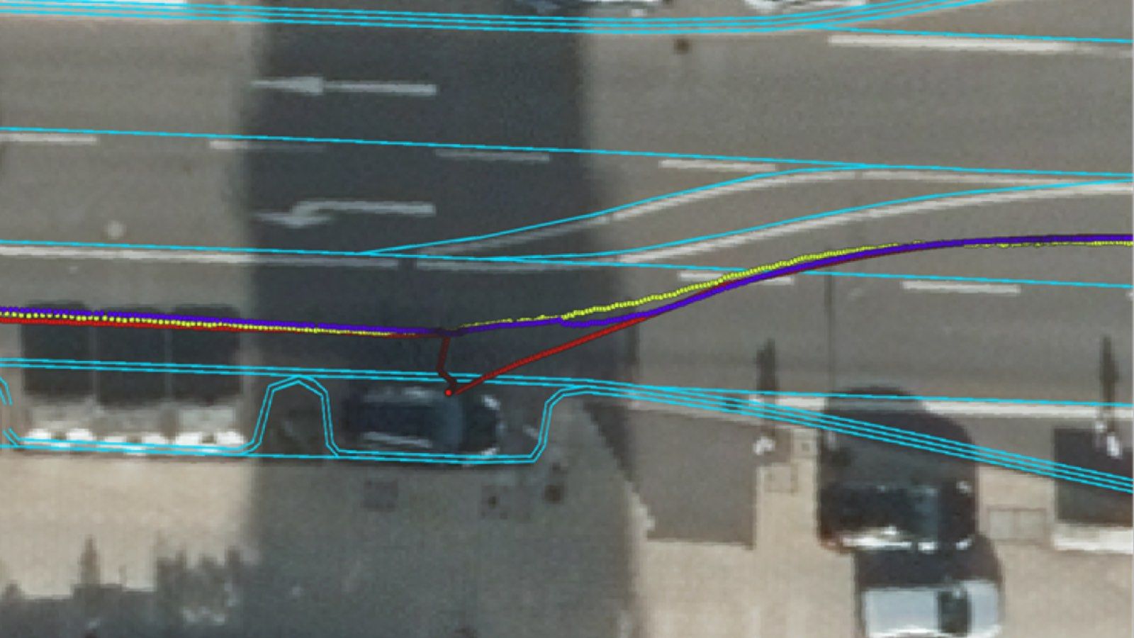
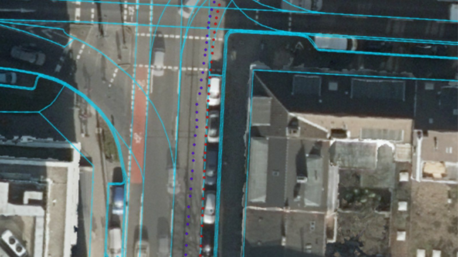
Rapid improvements in GNSS accuracy result in a noticeable shift in the solution, resembling a drift with an offset from the true position. Subsequently, the GNSS corrects this during a short interval.
Conversely, the fusion of GNSS and LiDAR-based GNSS maintains lateral stability, as seen on the picture below.
Even when GNSS accuracy remains consistently low throughout the drive, the fusion with LiDAR-based GNSS compensates effectively. This situation was intentionally induced by toggling RTK for the GNSS on and off. GNSS inaccuracies misplace the vehicle, while the fused solution provides a plausible trajectory, nearly centered in the lane.
Encountered Problems and Suggested Solutions
While not all encountered, issues were addressed in this project. The following insights highlight post-demo improvements:
- Carefully selecting valid GNSS points for trajectory generation is crucial for accurate LiDAR-based GNSS localization. Large sections lacking valid GNSS data can negatively impact LiDAR-based GNSS solutions due to SLAM algorithm drift. Choosing an appropriate threshold to distinguish valid from invalid trajectory points is essential. In cases where no suitable threshold exists, offline map generation allows manual correction of corresponding GNSS information.
- The fusion of different localization hypotheses using Kalman filters requires each hypothesis to provide a covariance matrix. Initially, a fixed covariance matrix was assumed for the demo, tailored to the specific test site. However, these fixed values proved insufficient in other test areas, such as Brunswig or Berlin. A heuristic was developed to estimate the covariance of the LiDAR-based GNSS solution (see Section 2.3), allowing for autonomous driving in various areas (both rural and urban) without parameter adjustments.
- Enhancing the robustness of LiDAR-based localization and reducing the LiDAR map's size involves removing potentially moving objects from the map. A neural network on point clouds (e.g., 3D-MiniNet) is considered for identifying and eliminating points corresponding to dynamic objects like vehicles, pedestrians, and bicycles.
Conclusion
In this project, Outsight's SLAM-based localization solution was effectively integrated into the Kalman filter-based framework and incorporated into world coordinates.
Additionally, the heuristic for supplying covariance information enhances the robust fusion of GNSS and LiDAR-based localization in world coordinates.
Read the full Research Paper on this application here.
Would you like to find out more about LiDAR applications for the ITS market and see how easy would be to make your own?